E893AB, Halo Series, H13 - 4K Ultra HD Smart Deterrence IP Camera: Installation Guide
This article provides instructions on how to install and connect 4K Ultra HD Smart Deterrence IP Camera (E893AB Series) to the NVR.
Before Installing
- Test your camera prior to selecting a permanent mounting location by temporarily connecting the camera and cable to your NVR.
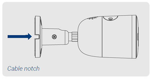
- Decide whether to run the cables through the wall/ceiling (drilling required) or along the wall/ceiling. If you run the cables along the wall/ceiling, you must run the cable through the cable notch located on the camera base (see figure below). This will keep the camera base flush to the surface when mounted.
Installing 4K Ultra HD Smart Deterrence IP Camera
-
Use the included mounting template to mark holes for the screws.
-
Use a 3/16” drill bit to drill holes for the mounting screws. Insert the included drywall anchors if you are installing the camera in drywall.
-
Connect cables as shown in Connecting 4K Ultra HD Smart Deterrence IP Camera below.
-
Feed the cable through the mounting surface or cable notch and mount the camera stand to the surface using the included screws.
-
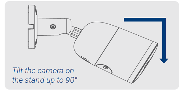
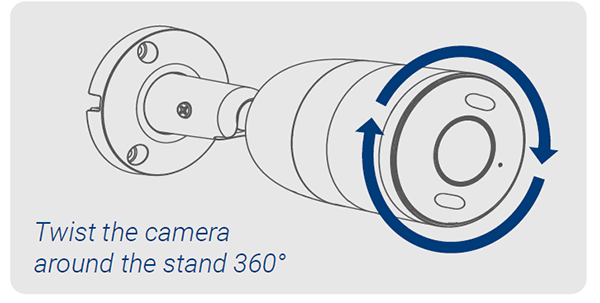
Use a Philips screwdriver to loosen the adjustment screw and adjust the camera position as needed.
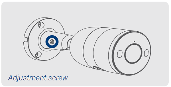
- Tighten the adjustment screw to secure the position.
- Remove the vinyl film from the camera lens when your installation is complete.
Connecting 4K Ultra HD Smart Deterrence IP Camera
Connect the cameras and cables to your NVR using one of the following two setup methods.
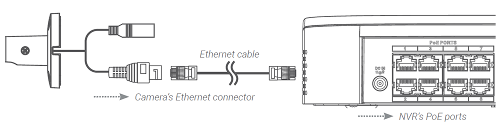
1. Connect cameras directly to the NVR (recommended).
Connect the Ethernet cable to the camera and then connect the other end of the Ethernet cable to the NVR’s PoE ports. The camera may take a minute to power on after being connected.
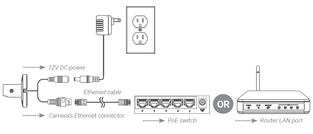
Note: A 12V DC power adapter (model#: ACCPWR12V1, not included) is only required if connecting the camera’s Ethernet cable to a router or switch that does not support PoE.
Notes:
- The smart deterrence camera is only compatible with select NVRs. For a list of compatible NVRs, visit lorextechnology.com/compatibility.
- You must connect the camera to a supporting H.265 NVR to take advantage of H.265 compression.
2. Connect cameras to a PoE switch or router on your network (not included).
Connect the Ethernet cable to the camera and then connect the other end of the Ethernet cable to a router or switch on your network. See your NVR manual for details on connecting the camera to your NVR using a router or switch.
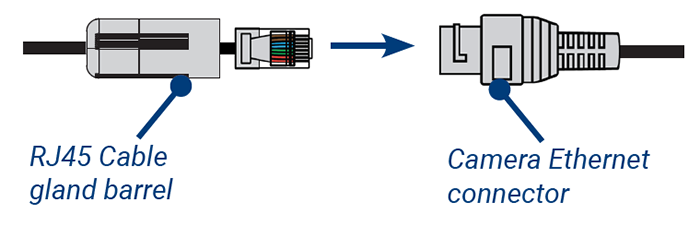
Using the RJ45 cable gland (optional)
The pre-attached RJ45 cable gland covers both the camera’s Ethernet connector and the RJ45 plug to provide weather-resistance and protection from dust, dirt and other environmental contaminants.
To use the RJ45 cable gland, twist the RJ45 cable gland barrel securely onto the camera’s Ethernet connector.
Tip: The RJ45 cable gland is weather-resistant. Seal the cap with silicone and/or electrical tape for additional sealing if it will be exposed to precipitation regularly.
Cable extension options
You can extend the Ethernet cable run for your camera up to 300ft (91m). To extend the cable run beyond 300ft (91m), a switch will be required (sold separately). Use an RJ45 coupler or a network switch (not included) to connect male ends of Ethernet cables together. We recommend using UL CMR approved cables available at lorex.com.
- Cable type: CAT5e (or higher) Ethernet cable
- Max. cable run distance: 300ft (91m)
- Max. number of extensions: 3